NuSIM Quectel BG95-M3 with UMTS & LTE EVB Kit
Introduction
What is special about nuSIM devices?
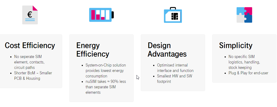
nuSIM devices do not need a SIM card like other NB-IoT DevKits. The information which is usually stored on the SIM card is allready integrated in the chipset of the nuSIM device.
This brings the following advantages:
More about nuSIM
If you are interested in the nuSIM topic you can get some more information here or get a free nuSIM DevKit here.
To start with the NuSIM NB-IoT module BG95-M3 from Quectel you can use the development board UMTS & LTE EVB Kit (see images below).
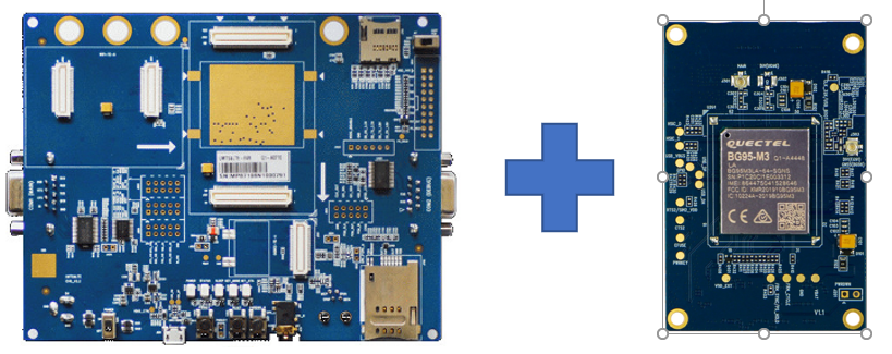
Quectel BG95-M3 with UMTS & LTE EVB Kit
Links*
| Titel | URL |
|---|---|
| Where can I get from? | https://www.tekmodul.de/produkt/bg95-m3-dvk/ |
| BG95 AT Commands Manual | https://github.com/iotcreators/doclib-downloads/blob/master/device-integrations/Quectel/BG95/Quectel_BG95BG77BG600L_Series_QCFG_AT_Commands_Manual_V2.0-1.pdf |
| BG95 Hardware Design | https://github.com/iotcreators/doclib-downloads/blob/master/device-integrations/Quectel/BG95/Quectel_BG95_Series_Hardware_Design_V1.3.pdf |
| More information about the BG95 | https://www.quectel.com/product/bg95.htm |
| More information about the UMTS & LTE EVB Kit | https://www.quectel.com/product/umtsevb.htm |
Links to the AT command samples:
- Query device information
- Setup network configuration
- Send "Hallo World" via UDP
- Receive "Hallo Device" via UDP
Setup the Device
In the following I will describe you how to setup your devkit so that you are able to send AT commands directly from your computer to the Cinterion module from Thales. To do so you need to
- connect your your devkit with your computer via USB
- press the power button
- execute AT commands on your devkit the first time.
Connect your devkit with your computer
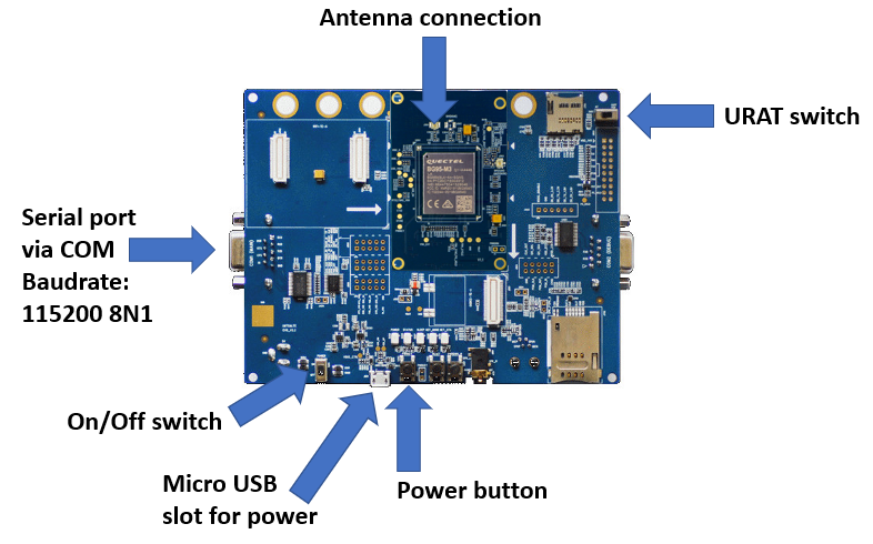
Your BG95-M3 DevKit will be connected with your compute by using the COM interface on the device and also needs power via micro USB. It can be accessed with a terminal program such as "putty" on Windows or "screen" or "minicom" on Linux.
In case you are working with Linux you are lucky. The USB/Serial drivers should be already available on your system and you don't need to install anything else.
In case you are using a Windows compute the driver will be automatically installed. If you have any trouble please download a FTDI VCP driver.
After you connected your BG95-M3 via USB with your computer you should find the device file
/dev/ttyUSB0 (or /dev/ttyACM0). It is automatically created when you connect your DevKit with your computer and if you disconnect it, your ENS22 DevKit disappears again.
Unfortunately I can not tell you how to enable the serial terminal connection via USB on Windows or Mac because I am only working with Linux. Sorry 😥.
On Linux
In case you have any problems to access the device file /dev/ttyACM0 because you don't have enough access privilages for this file execute the following command
$ sudo usermod -a -G dialout
If you access your devkit very shortly after you set it under power you should see the output
RDY
APP RDY
👍 👍 👍
When you can see the the RDY in the console you can pat yourself on the shoulder. Well Done You are ready now to play with your devkit and input AT commands.
Maybe you get echoed your input on the console. If this is the case you can deactivate the console echo by using `ATE0 command.
ATE0
OK
In case you have any troubles with any AT command and you get an ERROR response I recommand to configure the format of the error messages to long with the AT+CMEE command.
AT+CMEE=2
OK
AT Commands to query Device Information
In the following I describe some AT commands with which you can query essential infos from your devkit.
| AT Command | Description |
|---|---|
| ATI | Request product type number |
| AT+CGSN | Request IMEI (product serial number) |
| AT+CGMI | Request manufacturer |
| AT+CGMM | Request model identification |
| AT+CGMR | Request firmware version |
| AT+CCID | Request ICCID of SIM card |
| ATI9 | Request modem version & appl version |
ATI
@Quectel
BG95-M3
Revision: BG95M3LAR02A03
OK

AT+CGSN
8864475045308185
OK

AT+CGMI
Quectel
OK

AT+CGMM
BG95-M3
OK

AT+CGMR
BG95M3LAR02A03
OK

AT+CIMI
901405700073664
OK

AT+CCID
+CCID: 89882280000010296644
OK

ATI9
Quectel
BG95-M3
Revision: BG95M3LAR02A03
OK
Attach to NB-IoT Network
This chapter explains how you can attach your Quectel BG95-M3 devkit to the NB-IoT network.
If you are only interested in the conclusion of the AT commands to configure the network setup go to chapter "'AT Setup Commands" end of this document.
After you managed successfully to connect your devkit with your computer via USB cabel and to get access to it with your terminal program such as putty or screen you connect your devkit with the Telekom NB-Iot network.
In the following I describe you the basic AT commands with which your devkit should end-up with an IP address and being able to ping the UDP server of IoT Creators.
Attach to Telekom NB-IoT network
To attach to the NB-IoT network in most of the cases it is enough to
- Set the APN to cdp.iot.t-mobile.nl
- Set the mobile network operator such as T-Mobile Netherland or Telekom Deutschland
AT+CGDCONT=1,"IP","cdp.iot.t-mobile.nl"
# T-Mobile Netherland
AT+COPS=1,2,"20416",9

# Telekom Deutschland
AT+COPS=1,2,"26201",9

# T-Mobile Poland
AT+COPS=1,2,"26002",9
The list of all PLMN IDs (Public Land Mobile Network) you can find at https://en.wikipedia.org/wiki/Mobile_country_code
In the normal case the AT+COPS command can take up to 30 seconds.
If you want to know which network operators are visible or your devkit you can also use the AT+COPS=? command. Don't be supprised that this command blocks somtimes up to an minute.
AT+COPS=?
+COPS: (1,"E-Plus","E-Plus","26203",0),(1,"Vodafone.de","Vodafone","26202",0),(1,"Telekom.de","TDG","26201",0),(1,"Telekom.de","TDG","26201",9),,(0,1,2,3,4),(0,1,2)
OK
Configure some status control setting by using the AT+QCFG command. It is neccessary to set the band which is used by the modem as well. E.g. T-Mobile Netherlands and Telekom Deutschland use fequency band 8.
You can find all the frequency bands of European T-Mobile and Telekom networks in the chapter "IoT Configuration Paramter".
Normally you can not set the frquency band which shall be used by the radio module. Out of this reason you have to switch it off with the AT+CFUN=0 command before you set the band.
# Switch off the radio module
AT+CFUN=0

# Set the band to 8
AT+QCFG="band",0,0,80,1

#Configure RATs to be searched
AT+QCFG="nwscanmode",3,1

#Configure RAT searching sequence
AT+QCFG="nwscanseq",030201

#Configure Service Domain
AT+QCFG="servicedomain",1,1

#Set network category
AT+QCFG="iotopmode",1,1

# Switch on the radio module (or reboot the device)
AT+CFUN=1
Setting the fequency band for Quectel BG95-M3 is a bit special compared to other chipsets and modems. In most of the cases an AT command is provided to set the band just using direct numbers such as 8 or 20. In the following list you can see which number as the 4th paramter of the AT command needs to be used to set a specific frequency band.
| Band | Code |
|---|---|
| LTE B1 | 1 |
| LTE B2 | 2 |
| LTE B3 | 4 |
| LTE B4 | 8 |
| LTE B5 | 10 |
| LTE B8 | 80 |
| LTE B12 | 800 |
| LTE B13 | 1000 |
| LTE B18 | 20000 |
| LTE B19 | 40000 |
| LTE B20 | 80000 |
| LTE B26 | 2000000 |
| LTE B28 | 8000000 |
After setting the APN and the network operator you should reboot your devkit by power off and on again. After this you should wait ca. 30 seconds and use the AP+CGPADDR command to query the assigned IP address.
AT+CGPADDR
+CGPADDR: 1,10.0.2.34
OK
👍 CONGRATULATIONS 👍
If you can see an IP address as result of the
AT+CGPADDRcommand CONGRATULATIONS!! You just successfully attached your devkit to the T-Mobile/Telekom network.
Ping IoT Creators UDP server
After you connected successfully to the NB-IoT network you can test if you can reach the UDP server of IoT Creators. This actually really easy. You can do this with the AT+QPING command.
AT+QPING=1,"172.27.131.100"
OK

+QPING: 0,"172.27.131.100",32,611,255
+QPING: 0,"172.27.131.100",32,160,255
💪 Great 👏
If you can see an OK and the response lines you are in a very very good shape.
You laid the base the NB-IoT communication with IoT Creators platform.Now the fun can start 🏃
AT Commands to setup Network Configuration
# Query the ICCID from the SIM card to check if it properly inserted
AT+CIMI
901405700009292
OK

# Switch off the radio module
AT+CFUN=0

# Set the band to 8
AT+QCFG="band",0,0,80,1

#Configure RATs to be searched
AT+QCFG="nwscanmode",3,1

#Configure RAT searching sequence
AT+QCFG="nwscanseq",030201

#Configure Service Domain
AT+QCFG="servicedomain",1,1

#Set network category
AT+QCFG="iotopmode",1,1

# Switch on the radio module (or reboot the device)
AT+CFUN=1

# Set the APN
AT+CGDCONT=1,"IP","cdp.iot.t-mobile.nl"
OK

# Set the MNO (Germany, Telekom)
AT+COPS=1,2,"26201",9
OK

# Query the assigned IP address
AT+CGPADDR
+CGPADDR: 1,10.0.2.34
OK

# Ping the IoT Creators UDP server
AT+QPING=1,"172.27.131.100"
OK

+QPING: 0,"172.27.131.100",32,611,255
+QPING: 0,"172.27.131.100",32,160,255
Send and Receive via UDP
Send "Hello World"
Preliminary Work
Register your device first!
Make sure that you have registered your device with its IMEI at the IoT Creators portal BEFORE you send your first message to the UDP or CoAP server of IoT Creators.
If you forget, you will have problems to register your device afterwards. In this case please get in contact with IoT Creators support team.
Before you can send a "Hello World" UDP message from your device to IoT Creators platform make sure you did the following steps:
- Registered you device with the correct IMEI in the IoT Creators Portal.
To be sure that you used the correct IMEI you can query it with the AT command directly from the device. For BG95 related devices use AT commandAT+CGSNto query the IMEI. - Connect the device via USB cabel with your laptop.
- Start the terminal program such as putty (Windows) or screen (Linux) with a baudrate of 115200.
- Attach you device with the network
To test if your device is probably attached with the network you should run the command AT+CGPADDR and you should see a valid IP address.
AT+CGPADDR
+CGPADDR: 1,10.0.2.2

OK
You should only continue with the next steps if you have seen the IP address of the network attachment displayed on the console.
If you don't see the IP address unfortunatelly you have to start trouble shooting now 😢
As next you can Activate PDP context and open a UDP socket to the UDP server of the IoT Creators.
Open UDP socket to UDP server
AT+QIACT=1
OK

AT+QIOPEN=1,0,"UDP","172.27.131.100",15683
OK
+QIOPEN: 1,0
This AT command opens a UDP socket with:
- Context ID = 1,
- Connection ID = 0,
- Service type = UDP,
- Server IP address = 172.27.131.100,
- UDP port of the server = 15683
In all other AT commands which are related to this socket connection you should use 0 as connection id.
In case your AT+QIOPEN command doesn't return OK or +QIOPEN: 1,0 something went wrong.
At first you should double check if you can reach the UDP server with the AT+QPING command.
AT+QPING=1,"172.27.131.100"
OK

+QPING: 0,"172.27.131.100",32,3010,253
The ping result is returned by the first integer parameter of +PING: return. 0 means that every thing was fine. A value different 0 identies an error. You can use AT+QIGETERROR to get the error description.
Sending "Hello World" UDP Message to UDP Server
I recommand not to send plain text or binary data from the device to your backend applications or vice versa. You can use a hex or a base64 encoding format of data. In our sample we send Hello World as a hex converted string to the IoT Creators.
To convert Hello World you can use online tool http://string-functions.com/string-hex.aspx
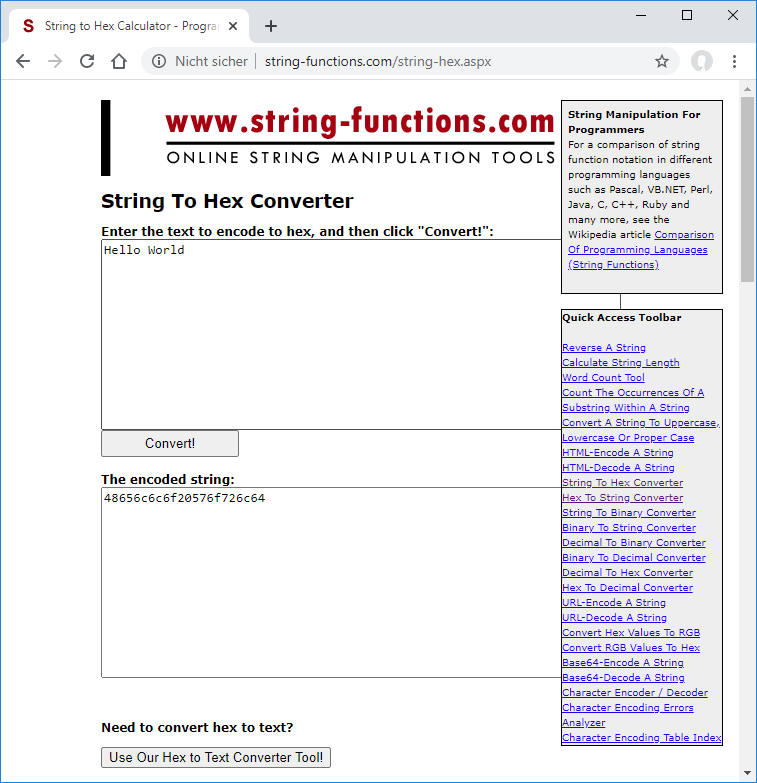
The hex string for Hello World is 48656c6c6f20576f726c64.
To let your device sent this message via UDP to the UDP server of IoT Creators you can use the following AT command:
AT+QISENDEX=0,"48616c6c6f20576f726c64"
OK
SEND OK
This AT command sends via the connection with the id 0 the message 48656c6c6f20576f726c64
If you see SEND OK on the device console CONGRATULATIONS! you just send your first UDP message from your device to an UDP server of IoT Creators.
The message length which is assigned to the command AT+QISENDEX as second parameter describes the length of the original message. It does NOT desribes the length of the hex message which has a length of 22 bytes.
As next we can change back to the project space of the IoT portal to check what has been received.
View the received Messages in IoT Creators Portal
For each device the IoT Creators Portal makes the laste received message available by showing it in the Payload column. In case of our Hello World message
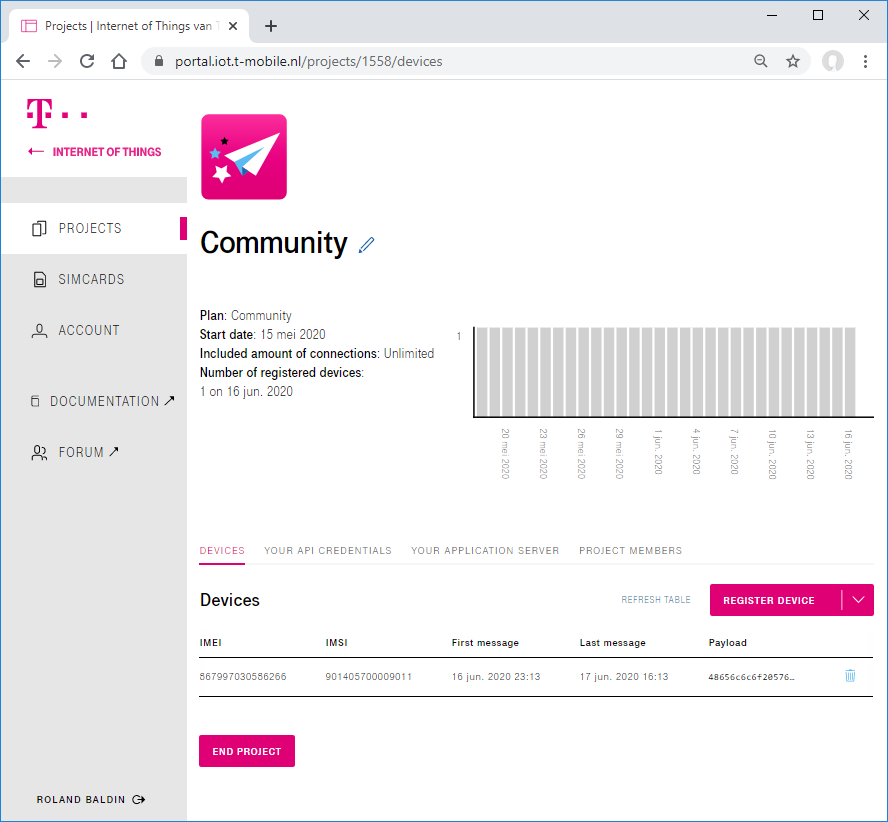
If you click on the payload the value of it is copied to the clipboard.
As already mentioned above it is a nice behaviour to transfer strings and binary data not as they are. It is better to encode them to hex or base64 for the transfer.
We sent our Hello World as hex encoded string on its way. Out if this reason we see in the IoT Creators Portal the string 48656c6c6f20576f726c64.
To decode the received message back from hex to a readable string we can use the online tool http://string-functions.com/hex-string.aspx.
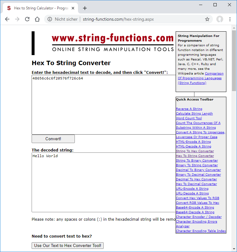
If you can decode your received message to Hello World **CONGRATULATIONS**! You just sent and receceived your first UDP message via NB-IoT.
AT Commands to send Hello World
# Activate PDP context
AT+QIACT=1

# Open local UDP socket
AT+QIOPEN=1,1,"UDP","172.27.131.100",15683,1001,0
OK
+QIOPEN: 1,0

# Send Hello World as Hex
AT+QISENDEX=1,"48616c6c6f20576f726c64"
OK
SEND OK

# Close the socket
AT+QICLOSE=1
OK
Receive "Hallo Device"
In this chapter you will receive the previous posted "Hello Device" downlink message with your device.
Preliminary Work
Before you can receive a "Hello Device" UDP message from your device to IoT Creators platform make sure you did the following steps:
- Registered you device with the correct IMEI in the IoT Creators Portal.
To be sure that you used the correct IMEI you can query it with the AT command directly from the device. For BG95-M3 related devices use AT commandAT+CGSNto query the IMEI. - Connect the device via USB cabel with your laptop.
- Start the terminal program such as putty (Windows) or screen (Linux) with a baudrate of 115200.
- Attach your device with the network
To test if your device is probably attached with the network you should run the command AT+CGPADDR and you should see a valid IP address.
AT+CGPADDR
+CGPADDR: 1,10.0.2.2

OK
You should only continue with the next steps if you seen the IP address of the network attachment displayed on the console.
If you don't see the IP address unfortunatelly you have to start trouble shooting now :(
Post Downlink Message to the API of IoT Creators SCS
Before you can receive a message you have to Post the Downlink Message. To do so follow the steps in the Chapter Post Downlink Message to the API of IoT Creators SCS
Receive Downlink Message on the Device
As mentioned before IoT Creators queues the posted downlink messages for a device until the device sends an uplink message. After IoT Creators received the uplink message it delivers the queued downlink messages to the device.
After you opened the socket to the UDP server of IoT Creators with the AT+QIOPEN go to the console of the device and send "i am alive" heartbeat message to IoT Creators.
AT+QISENDEX=0,"6920616d20616c697665"
SEND OK

+QIURC: "recv",0
As you can see in the AT command console above it appears a +QIURC: "recv",0 command to notify that data has been received on the socket "0".
To retrieve the data you can use the AT command AT+QIRD=0. This command tries to retrieve the bytes from socket 0.
AT+QIRD=0

+QIRD: 24
48656c6c6f20446576696365

OK
CONGRATULATIONS!! You send your first downlink message from the cloud to the device.
The whole story works exactly the same if you have your device switched off, and send first the downlink message. After this you can switch on your device, perform the alive-ping and get the received downlink message.
AT Commands to receive Hello Device
# Open the UDP socket to the server of IoT Creators
AT+QIOPEN=1,10"UDP","172.27.131.100",15683,1001,0
OK
+QIOPEN: 0,0

# Send "i am alive" heartbeat message
AT+QISENDEX=1,"6920616d20616c697665"
SEND OK

+QIURC: "recv",0

# Read message
+QIRD: 24
48656c6c6f20446576696365
OK

# Close the socket
AT+QICLOSE=0
OK
Updated about 4 years ago
