SIMCom SIM7070G
Learn how to setup and integrate SIM7070G Waveshare Dev-Kit with IoT Creators NB-IoT network and Data Provisioning Service (SCS)
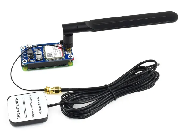
SIM7070G
Links
Links to the AT command samples:
- Query device information
- Setup network configuration and verification
- Send "Hallo World" via UDP
- Receive "Hallo Device" via UDP
Setup the Device
In the following I will describe you how to setup your devkit so that you are able to send AT commands directly from your computer to the SIMCom modem.
Connect your Dev-Kit with your computer
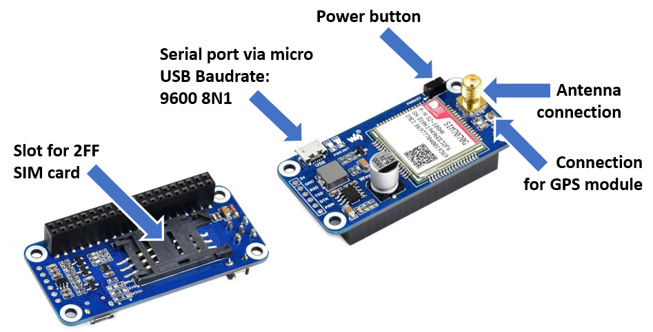
Your devkit will be connected with your compute by using mini USB and can be accessed with a terminal program such as "putty" on Windows or "screen", "miniterm" or "minicom" on Linux.
In case you are working with Linux your are lucky. The USB/Serial drivers should be already available on your system and you don't need to install anything else.
Connect the GPS module and the antenna as in the first picture of this guide. Insert your SIM card and plug in the micro USB cable.
After you connected your devkit via USB with your computer you need to push the power button. When the second LED starts to flash, your Dev-Kit is ready to use.
Now you should find the device file /dev/ttyUSB5 on your computer. It is automatically created when you connect your Dev-Kit with your computer and if you disconnect it your Dev-Kit disappears again.
Execute AT commands on your Dev-Kit the first time.
To execute AT commands on your Dev-Kit you need start on your computer a terminal program such as putty on Windows or miniterm, minicom or screen on Linux and connect it with your Dev-Kit via the serial USB line. After this you can send AT commands to the modem of your Dev-Kit.
In the following I will explain to you how to do this stuff on Linux by using the miniterm and to send those AT commands to the modem to query device product and IMEI information.
Connect your devkit with your Linux computer via terminal program minterm
In case miniterm is not already installed on your computer you can install it with
After that you can configure minicom by executing the following command. It will use your port /dev/ttyUSB5, activate the echo with -e and use the default baudrate of 9600bps, 8 bits, no parity bit and 1 stop bit.
> $ miniterm /dev/ttyUSB5 -e
After executing it will look like this:

Now you should be able to deactivate the echo with the following AT-command:
ATE0
Congratulations
If you reached this point you equipt your SIM7070G with the capabiltiy to pass your AT commands from the serial USB terminal interface directly to the modem.
Now the fun begins! 😃 😃
AT Commands to get IMEI, IMSI and other product information from your devkit
In the following various AT commands are shown to query the IMEI and other product information from your devkit.
# Request IMEI
AT+CGSN

<<<YOUR-IMEI>>>

OK

# Request IMSI of the SIM card
AT+CIMI

<<<YOUR_IMSI>>>

OK

#Request CCID of the SIM card
AT+CCID

<<<YOUR_CCID>>>

OK


# Request manufacturer identification
AT+CGMI

SIMCOM_Ltd

OK

# Rquest model identification
AT+CGMM

BC95SIMCOM_SIM7070

OK

# Request firmware version identification
AT+CGMR

Revision:1951B08SIM7070

OK

# Request prodct type number
ATI

R1951.04

OK
Attach to the NB-IoT Network
This chapter explains how you can attach your SIM7070G Dev-Kit to the NB-IoT network.
If you are only interested in the conclusion of the AT commands to configure the network setup go to chapter "'AT Commands Only"
Before you send any UDP or COAP message to IoT Creators make sure you registered the device IMEI before.
If you forget, you will have problems to register your device afterwards. In this case please get in contact with IoT Creators support team.
A few assumptions and notes before starting with this manual
- You should be able to send AT commands to your devkit with a terminal program such as putty, screen, minicom, etc.
- Your device is on the latest firmware
- Be gentle to your device and have some patience. After each AT command he/she/it needs a few seconds to execute the command and respond
In the following we will walk through together the AT commands with which you can perform the following actions:
- Setup network configuration of you devkit.
- Attach to the network and verify your network configuration.
- Ping an IP address.
Setup Network Configuration
Set the band with to NB-IoT
AT+CBANDCFG="NB-IOT",8
Set APN of IoT Creators
AT+CGDCONT=1,"IP","cdp.iot.t-mobile.nl"

OK

AT+CNCFG=0,1,"cdp.iot.t-mobile.nl"

OK
Select the network operator of your choice with +COPS command manually (1) by given the numeric identification (2) of the operator ("26201", "20416", "26002", etc.) (https://docs.iotcreators.com/docs/telekom-iot-networks-in-europe)
AT+COPS=0,2,"20416",9
AT+COPS=0,2,"26201",9
AT+COPS=0,2,"26002",9
👍 Great! Your setup of network configuration is complete now.
The next step is it to test if it is correct and if your Dev-Kit is able to attach the network with it.
Good Luck 😏
You can check if your device is attached to the network with the following AT-command:
AT+CGATT?

+CGATT: 1

OK
As next we will verify if your Dev-Kit is actually attached to the network with checking the IP address.
AT+CGPADDR

+CGPADDR: 1,"<<<YOUR_IP_ADDRESS"
OK
😠 What to do if it doesn't work 👿
If you are not able to get established a network attachment double check the following
- Did you configure the correct APN?
- Did you configure the correct mobile network operator in your country?
- Did you make sure your SIM card has active roaming in case you are not in the home country of your network operator?
AT Commands to query Network Information
In the following I show you some more AT commands with which you can query other information regarding mobile connection status.
# Query if the devkit is attached to the network
AT+CGATT?
+CGATT: 1
OK

#Check IP address
AT+CGPADDR
+CGPADDR: 1,<<<YOUR_IP_ADDRESS>>>

# Query the configured MNO (Mobile Network Operator)
AT+COPS?
+COPS: 0,2,"26201"
OK

# Query the configured APN
AT+CGDCONT?
+CGDCONT: 1,"IP","cdp.iot.t-mobile.nl","0.0.0.0",0,0,0
+CGDCONT: 2,"IPV4V6","ims","::",0,0,0
OK

# Query signal power and quality
# Power should be between 0-31 and NOT 99. 99 means "no network detactable"
# Quality should be between 0-9. 99 means not know or not detactable.
AT+CSQ
+CSQ: 10,9
OK
Ping the first IP address
With the AT+CGPADDR command you could query the current IP address of your devkit. But you still not know if your devkit is able communicate in the IP network correctly.
To test this you should ping the UDP server of IoT Creators platform with the +SNPING4 command.
AT+SNPDPID=0
AT+CNACT=0,1
AT+SNPING4="172.27.131.100",5,1,20000

+SNPING4: 1,172.27.131.100,7777
+SNPING4: 2,172.27.131.100,3380
+SNPING4: 3,172.27.131.100,3897
+SNPING4: 4,172.27.131.100,2765
+SNPING4: 5,172.27.131.100,2748

OK
👍 Congratulations 👍
If you reached this point and if you were able to ping successfully the IoT Creators' UDP server you reached a very important milestone.
Experience has shown that most of the problems arise during the Dev-Kit commissioning and the first attachment with the network.
The rest journey -the next steps of the tutorial- will be easy 😏
AT Commands Only
#######################################################################
# Network attach
#######################################################################
# Set the APN
AT+CGDCONT=0,"IP","cdp.iot.t-mobile.nl"

# Set the bands
AT+CBANDCFG="NB-IOT",8

# select an operator DE:"26201", NL:"20416"
AT+COPS=0,2,"26201"

#######################################################################
# Network attach verification
#######################################################################
# Check IP address
AT+CGPADDR

# Check if attached to network
AT+CGATT?

# Check MNO
AT+COPS?

# Check APN
AT+CGDCONT?

# Check signal strength and qualitay
AT+CSQ

# Extended error report
AT+CEER

#######################################################################
# Ping UDP server of IoT Creators
#######################################################################
AT+SNPDPID=0
AT+CNACT=0,1
AT+SNPING4="172.27.131.100",5,1,20000
Send and Receive data via UDP
In the following chapters I will explain to you how you can send a "Hello World" message from the device to the IoT Creators SCS and how you can receive a a "Hello Device" message on your devkit from IoT Creators SCS.
Send "Hello World"
Register your device first!
Make sure that you have registered your device with its IMEI at the IoT Creators portal BEFORE you send your first message to the UDP or CoAP server of IoT Creators.
If you forget, you will have problems to register your device afterwards. In this case please get in contact with IoT Creators support team.
Welcome to this step of tutorial. You probably ended up here because you could successfully connect your devkit to the network.
Before you continue make sure your device has an IP address assigned and you can ping the UDP server of IoT Creators. You test both with the +CGPADDR and the +SNPING4 command.
AT+CGPADDR
+CGPADDR: 0,"<<<YOU_IP_ADDRESS>>>"
OK

AT+SNPDPID=0
AT+CNACT=0,1

AT+SNPING4="172.27.131.100",5,1,20000

+SNPING4: 1,172.27.131.100,7777
+SNPING4: 2,172.27.131.100,3380
+SNPING4: 3,172.27.131.100,3897
+SNPING4: 4,172.27.131.100,2765
+SNPING4: 5,172.27.131.100,2748

OK
In the next steps you will
- Open local UDP socket to send UDP messages.
- Create a hex coded "Hello World" message.
- Send the hex coded "Hello World" message to the UDP server of IoT Creators.
- Verify if the messages has been arrived at the IoT Creators platform.
Open local UDP Socket to send message
To send UDP messages to a UDP server you need to activate PDP. The returned value of this command ("0" in the sample below) represents the identifier.
AT+CACID=0,1

OK

+APP PDP: 0,ACTIVE
Afterwards you are able to open a UDP socket:
AT+CAOPEN=0,0,"UDP","172.27.131.100",15683

+CAOPEN: 0,0

OK
Create a HEX coded "Hello World" Message
I recommand not to send plain text or binary data from the device to your backend applications or vice versa. You can use a hex or a base64 encoding format of data. In our sample we send Hello World as a hex converted string to the IoT Creators.
To convert Hello World you can use online tool http://string-functions.com/string-hex.aspx
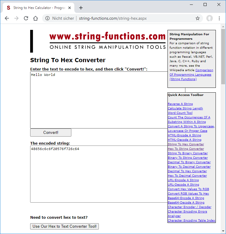
Tool to convert "Hello World" string to hex format.
The hex string for Hello World is 48656c6c6f20576f726c64.
Sending HEX coded "Hello World" Message to UDP Server
To let your device sent this message via UDP to the UDP server of IoT Creators you can use the +CASEND command as shown in the following.
The +NSOST command returns the socket identification as a first digiti and the length of successfully sent data as second digit.
AT+CASEND=0,11

>48656c6c6f20576f726c64

0,11
OK
CONGRATULATIONS 👏 🍰
If you see OK on the device console CONGRATULATIONS! you just send your first UDP message from your device to an UDP server of IoT Creators.
The data length which is assigned to the command
AT+CASENDdescribes the length of the original data. It does NOT desribes the length of the data in hex format which has a length of 22 bytes in the "Hello World" case.
View the received Messages in IoT Creators Portal
For each device the IoT Creators Portal makes the laste received message available by showing it in the Payload column. In case of our Hello World message
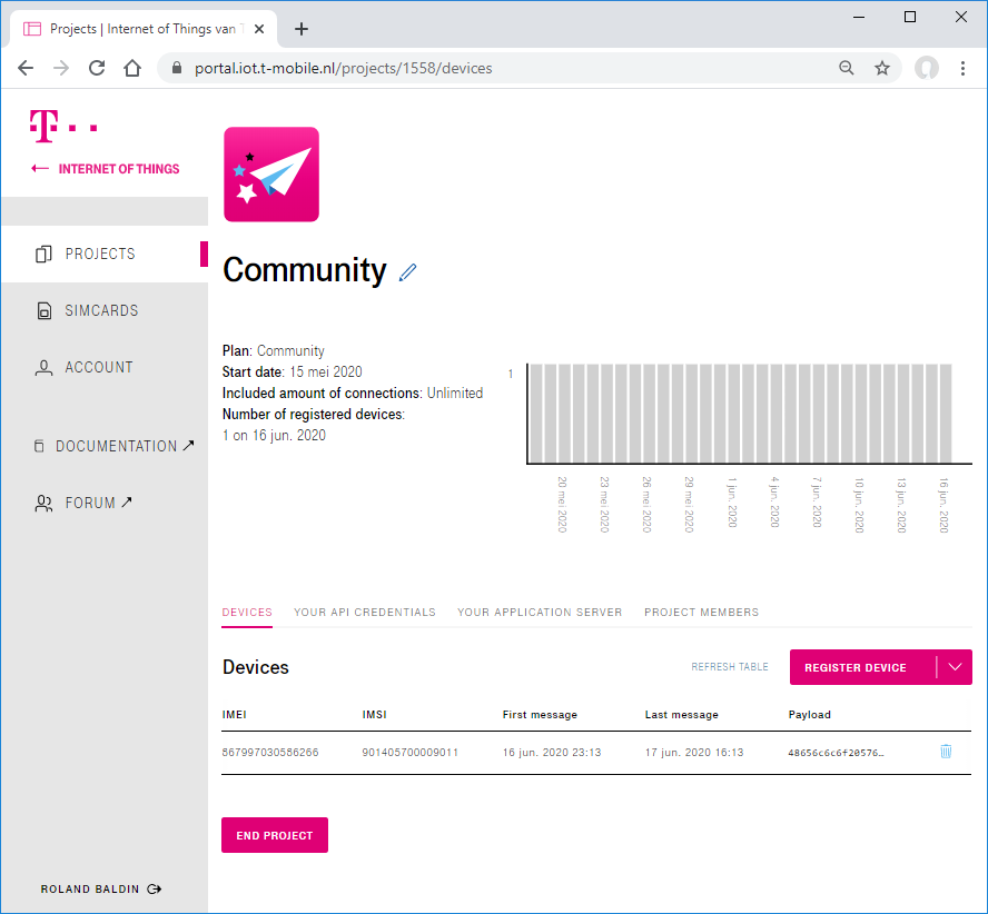
Project view of IoT Creators portal with device and last sent data.
If you click on the payload the value of it is copied to the clipboard.
Click on payload to copy into clipboard.
As already mentioned above it is a nice behaviour to transfer strings and binary data not as they are. It is better to encode them to hex or base64 for the transfer.
We sent our Hello World as hex encoded string on its way. Out if this reason we see in the IoT Creators Portal the string 48656c6c6f20576f726c64.
To decode the received message back from hex to a readable string we can use the online tool http://string-functions.com/hex-string.aspx.
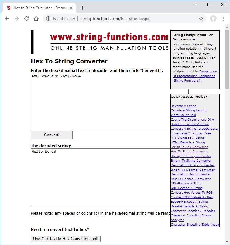
Online tool to convert hex to string.
👏 CONGRATULATIONS 👏 🍰
If you can decode your received message to Hello World **CONGRATULATIONS**! You just sent your first UDP message from your device via NB-IoT to IoT Creators platform.
Maybe you have to send the first message twice. The first message will be considered as a registration message, so the it will not be forwarded to the GUI.
You can close the socket with AT+CACLOSE
AT+CACLOSE=0
OK
AT Commands to send Hello World
#Activate PDP
AT+CACID=0,1
OK
+APP PDP: 0,ACTIVE

#Open UDP socket
AT+CAOPEN=0,0,"UDP","172.27.131.100",15683
+CAOPEN: 0,0
OK

# Send UDP message to UDP server via socket=0
AT+CASEND=0,11
>48656c6c6f20576f726c64
0,11
OK

# Close socket=0
AT+CACLOSE=0
OK
Receive "Hello Device"
Welcome back to the tutorial 👍.
In this step I will explain you how you can receive the "Hello Device" downlink message 48656c6c6f20446576696365 via UDP which you have posted before to the IoT Creators platform.
The downlink message which you posted to IoT Creators API before is queued by the IoT Creators platform. The queued downlink message is sent to the device after IoT Creators platform received the uplink message from the device.
In this tutorial you will perform the following steps:
- Open local UDP socket.
- Send a "i am alive" heartbeat message via UDP to the UDP server of IoT Creators.
- Receive the previous queued "Hello Device" message from the IoT Creators platform.
Send "i am alive" heartbeat message and receive downlink message
After you verified the network attach of your device you can open the UDP socket on your device and send a "i am alive" heartbeat message to the UDP server of IoT Creators. The message should be in hex format.
#Activate PDP
AT+CACID=0,1
OK
+APP PDP: 0,ACTIVE

AT+CAOPEN=0,0,"UDP","172.27.131.100",15683
+CAOPEN: 0,0
OK

# Send UDP message to UDP server via socket=0
AT+CASEND=0,10
>6920616d20616c697665
0,10
OK
Now you can send the "i am alive" message:
AT+CASEND=0,10
>6920616d20616c697665
0,10
OK
The "i am alive" message causes the UDP server of the IoT Creator portal to send out the previous queued "Hallo Device" message to the device. You can receive this message with AT+CARECV
AT+CARECV=0,12

+CARECV:48616C6C6F20446576696365

OK
To decode the hex data 48616C6C6F20446576696365 into a readable string you can use the online tool http://string-functions.com/hex-string.aspx.
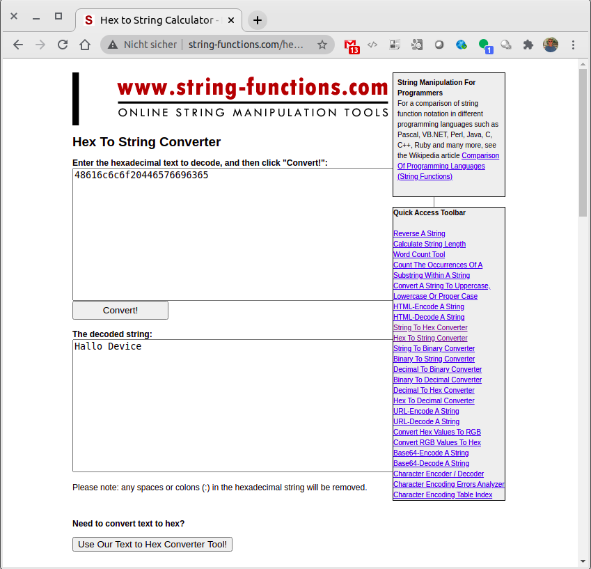
Online tool to decode hex data to string data.
Now you can close the socket with AT+CACLOSE
AT+CACLOSE=0
OK
Downlink only possible after uplink
If you try to send a downlink message to a device that has not send any uplink messages you will receive the error : Serial number not found.
After sending an uplink message the device registration is completed and downlinking will work.
AT Commands to receive "Hello Device"
#Test if the device has an IP address
AT+CGPADDR
+CGPADDR: 0,"<<<YOUR_IP_ADDRESS>>>"
OK

#Ping IoTCreator's UDP server
AT+SNPING4="172.27.131.100",5,1,20000
+SNPING4: 1,172.27.131.100,7777
+SNPING4: 2,172.27.131.100,3380
+SNPING4: 3,172.27.131.100,3897
+SNPING4: 4,172.27.131.100,2765
+SNPING4: 5,172.27.131.100,2748
OK

#Activate PDP
AT+CACID=0,1
OK
+APP PDP: 0,ACTIVE

# Open local UDP socket
AT+CAOPEN=0,0,"UDP","172.27.131.100",15683
+CAOPEN: 0,0
OK

# Send "i am alive" message to UDP server
AT+CASEND=0,10
>6920616d20616c697665
0,10
OK

AT+CARECV=0,12
+CARECV:48616C6C6F20446576696365
OK

# Receive data
AT+NSORF=0,12
0,"172.27.131.100",15683,12,"48616C6C6F20446576696365",0
OK

#Close socket
AT+CACLOSE=0
OK
Updated about 4 years ago
