SODAQ SARA AFF R410M
Learn how to setup and integrate SODAQ SARA AFF R410M with IoT Creators via LTE-M and send and receive messages via MQTT
Introduction
To help developers to start with the LTE-M module "uBlox SARA-R410M" you can use the developer kit (devkit) SODAQ SARA Arduino Form Factor (AFF) R410M (see https://shop.sodaq.com/sodaq-sara-aff-r410m.html).
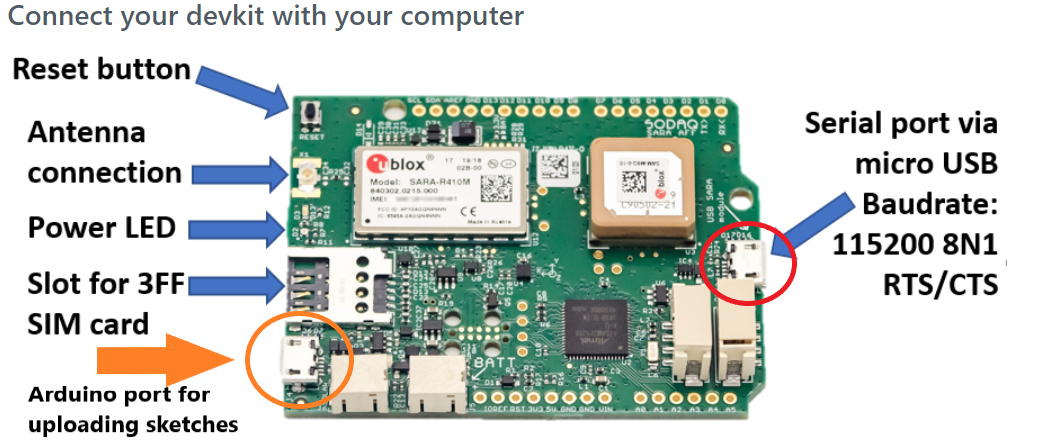
SODAQ SARA Arduino Form Factor (AFF) R410M
Links
| Titel | URL |
|---|---|
| Where can I get it from? | https://shop.sodaq.com/sodaq-sara-aff-r410m.html |
| Product info @SODAQ | https://learn.sodaq.com/Boards/Sara_AFF |
| Getting started @SODAQ | https://learn.sodaq.com/getting_started |
| SARA-R4 series AT Commands @uBlox | https://www.u-blox.com/sites/default/files/SARA-R4ATCommands%28UBX-17003787%29.pdf |
Links to the AT command samples:
- Query device information
- Setup network configuration and verification
- Communicate with a MQTT broker
Setup the Device
In the following I will describe you how to setup your devkit so that you are able to send AT commands directly from your computer to the ublox modem. To do so you need to
- connect your your devkit with your computer via USB,
- install AT command passthrough sketch on your devkit and
- execute AT commands on your devkit the first time.
Connect your devkit with your computer
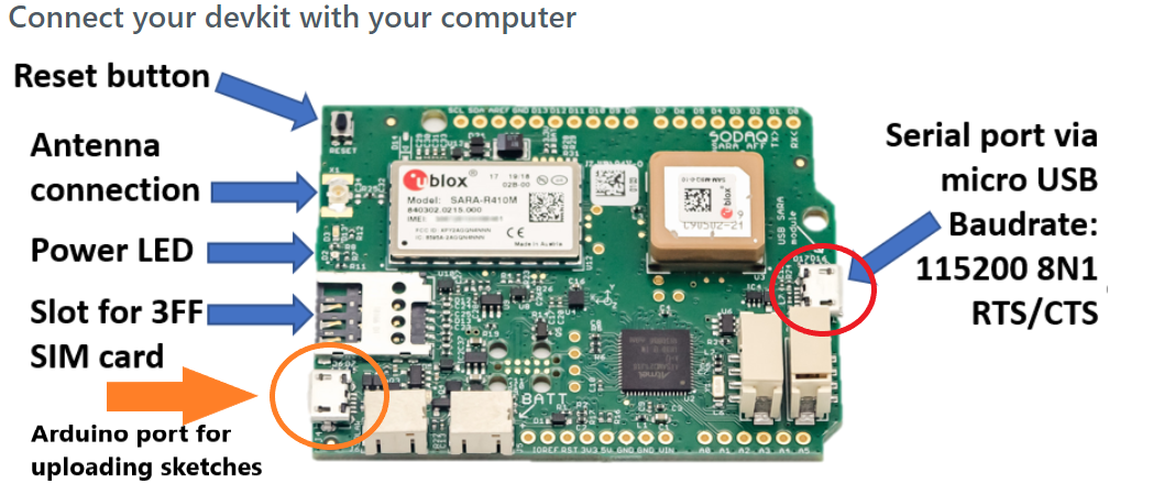
Parts of the SODAQ SARA AFF 410M
Your devkit will be connected with your compute by using mini USB and can be accessed with a terminal program such as "putty" on Windows or "screen" or "minicom" on Linux.
In case you are working with Linux your are lucky. The USB/Serial drivers should be already available on your system and you don't need to install anything else.
After you connected your devkit via USB with your computer you should find the device file
/dev/ttyACM0 (or /dev/ttyUSB0 ; /dev/ttyUSB1). It is automatically created when you connect your devkit with your computer and if you disconnect it your devkit disappears again.
Unfortunately I can not tell you how to enable the serial terminal connection via USB on Window or Mac because I am only working with Linux. Sorry 😞.
Install AT command passthrough sketch on your devkit
In contrast to other devkits the SODAQ SARA AFF R410M is not delivered to you with an out-of-the-box capability that AT commands on the serial USB interface are directly passed through to the modem. Out of this reason you need to install the passthrough sketch for SODAQ on your devkit first
Install Arduino IDE on your computer
The passthrough sketch is Arduino source code written in "C". To compile and to upload it to your devkit you need to install the Arduino IDE on your computer first.
You can download the latest version of Arduino IDE from
Make sure you install or update the latest version of Arduino IDE.
When your Arduino IDE is installed, it might be necessary to restart your computer. In some cases, if you don’t restart your computer, the IDE will not launch.
Configure Arduino IDE for SODAQ SARA AFF R410M
After you installed or updated your Arduino IDE you need to configure your Arduino IDE with the Board Files for the SODAQ SARA AFF R410M. Please follow the SODAQ setup guide which you can find at
Compile and upload passthrough sketch to your devkit
As mentioned before the passthrough sketch is "C" source code for Arduino. The sketch which passes the AT commands from the serial terminal interface directly through to the modem you can get from
https://learn.sodaq.com/Boards/Sara_AFF/Examples/passthrough/.
To compile and upload the sketch perform the following steps:
- In Linux shell: Start Arduino IDE on your computer by executing the command arduino.
- In Arduino IDE: Create a new sketch by executing File/New.
- In Arduino IDE: Replace the complete default code in the new sketch with the code which you can copy from https://learn.sodaq.com/Boards/Sara_AFF/Examples/passthrough/ (see image below)
- In Arduino IDE: Compile the code by executing Sketch/Compile ( see image below)
- On your Computer: Connect the devkit with your compute via USB
- In Arduino IDE: Upload the compiled sketch by executing Sketch/Upload (see image below)
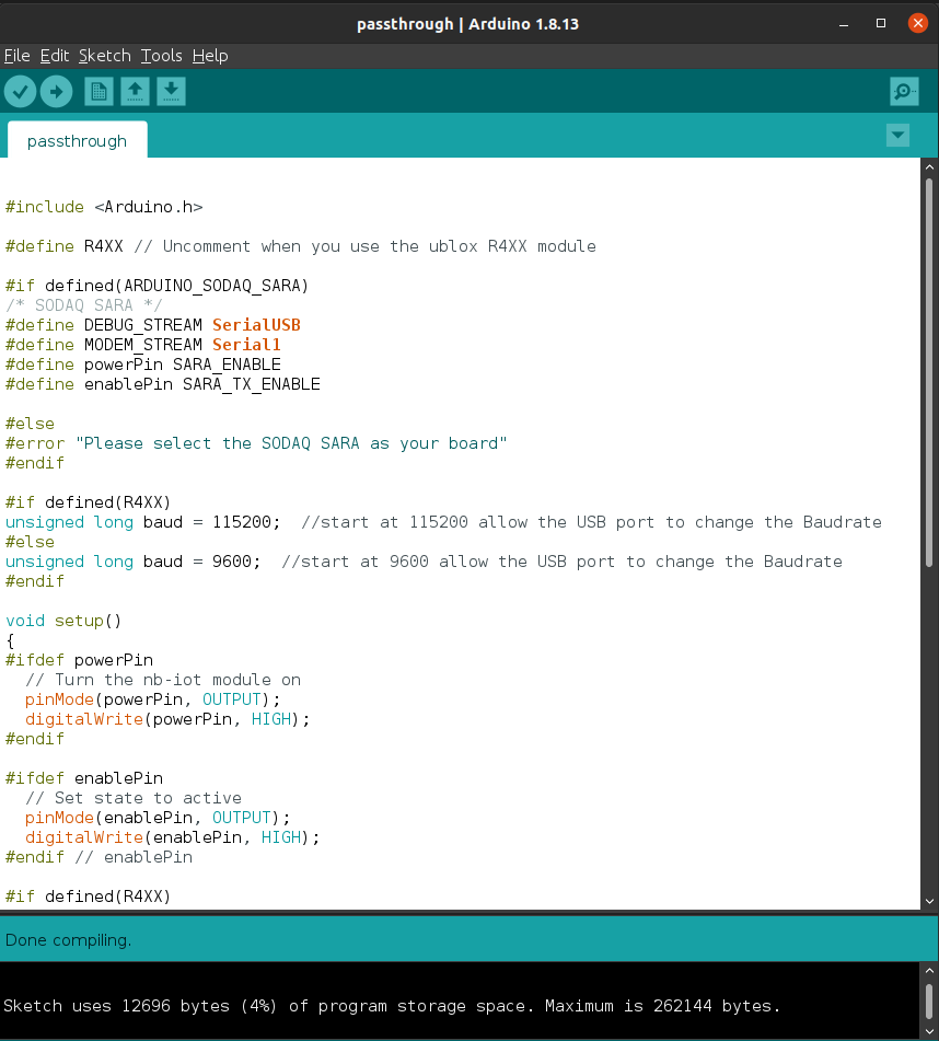
Successfully compiled "C" source code of passthrough sketch.
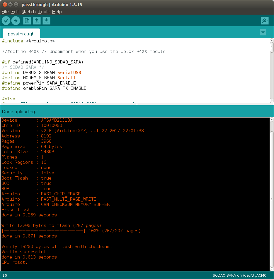
Successfully uploaded sketch to the devkit.
Execute AT commands on your devkit the first time.
To execute AT commands on your devkit you need start on your computer a terminal program such as putty on Windows or minicom or screen on Linux and connect it with your devkit via the serial USB line. After this you can send AT commands to the modem of your devkit.
You can also use the integrated serial monitor available in arduino IDE, only when connecting through arduino micro-usb dedicated port.
In the following I will explain to you how to do this stuff on Linux by using the minicom and to send those AT commands to the modem to query device product and IMEI information.
Connect your devkit with your Linux computer via terminal program minicom
In case minicom is not already installed on your computer you can install it with
$ sudo apt-get install minicom
After that you can configure minicom by executing
$ sudo minicom -s
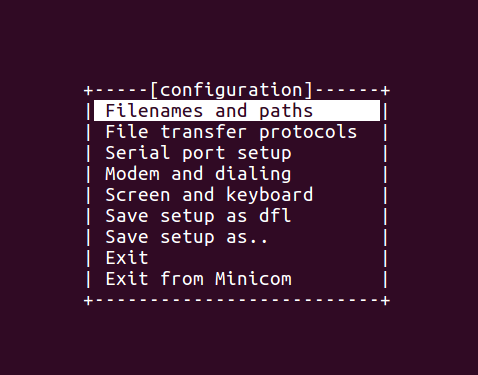
Main configuration menu of minicom.
It is important that you run the configuration of minicom as root because the resulting configuration file will be stored in the directory /etc/minicom to which root has only write permissions.
In the minicom configuration menu change the following settings:
- Enter Serial port setup
- Set Serial Device to /dev/ttyACM0
- Set the baudrate (Bps/Par/Bits) to 115200 8N1
- Enter Screen and keyboard
- Set Local echo to Yes
- Enter Save setup as
- Give r410m as the name to save the configuration
- Enter Exit from Minicom
After configuring minicom for your SODAQ devkit you can start minicom with the configuration *r410m'* which just created before.
$ minicom sodaq
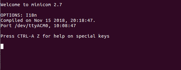
In case you have any problems to access the device file /dev/ttyACM0 because you don't have enough access privilages for this file execute the following command
$ sudo usermod -a -G dialout YOUR-USER-NAME
As very first AT command you should input the command AT. This command shall always return OK. If not, there is something wrong.
AT

OK
Congratulations
If you reached this point you equipt your SODAQ SARA AFF R410M with the capabiltiy to pass your AT commands from the serial USB terminal interface directly through to the ublox modem.
Now the fun begins! 😃 😃
AT Commands to get IMEI, IMSI and other product information from your devkit
In the following various AT commands are shown to query the IMEI and other product information from your devkit.
If you deal with AT commands for the ublox SARA R4 series I always recommand to use the ublox AT command documentation
closed to you.
# Request IMEI
AT+CGSN=1

356726101344240

OK

# Request IMSI of the SIM card
AT+CIMI

901405700025364

OK

# Request SIM card identification number
AT+CCID

+CCID: 89882280000008986545

OK

# Request manufacturer identification
AT+CGMI

u-blox

OK

# Rquest model identification
AT+CGMM

SARA-R410M

OK

# Request firmware version identification
AT+CGMR

L0.0.00.00.05.08 [Apr 17 2019 19:34:02]

OK

# Request prodct type number
ATI

Manufacturer: u-blox
Model: SARA-R410M-02B
Revision: L0.0.00.00.05.08 [Apr 17 2019 19:34:02]
SVN: 03
IMEI: 356726101344240


OK

# Request the version of the modem and the application
ATI9

L0.0.00.00.05.08,A.02.04

OK
Troubleshooting
It may happen that the modem, after about 6 seconds or so after booting up, stop responding when the sim is inserted. That might be because the modem was already configured to connect to another network that is not currently available, leaving the modem in infinite wait. In order to fix this issue, please send command to reset the selected network:
AT+COPS=0,0
Attach to the LTE-M/NB-IoT Network
This chapter explains how you can attach your SODAQ SARA AFF R410M devkit to the LTE-M or NB-IoT network. I recommend to read the chapter "Setup SODAQ SARA AFF R410M" first.
If you are only interested in the conclusion of the AT commands to configure the network setup go to chapter AT Commands Only
Currently we are still working on a LTE-M supporting server which means that you can not send any message to your Starterkit Overview like usually with a NB-IoT device.
A few assumptions and notes before starting with this manual
- You should be able to send AT commands to your devkit with a terminal program such as putty, screen, minicom, etc.
- Your device is on the latest firmware
- Be gentle to your device and have some patience. After each AT command he/she/it needs a few seconds to execute the command and respond
In the following we will walk through together the AT commands with which you can perform the following actions:
- Setup network configuration of you devkit.
- Attach to the network and verify your network configuration.
- Ping an IP address.
Setup Network Configuration
Set a preconfigured Mobile Network Operator profile with the +UMNOPROFcommand.
AT+UMNOPROF=1

OK
If you want to connect to LTE-M, please set the URAT to LTE-M with the+URATcommand.
AT+URAT=7

OK
Otherwise, if you want to connect to NB-IoT, please set the URAT to NB-IoT with the+URATcommand.
AT+URAT=8

OK
Set the APN of IoT Creators with +CGDCONT to m2m.public.nl.
AT+CGDCONT=0,"IP","m2m.public.nl"

OK
Set the EPS network registration status with +CEREG command.
AT+CEREG=3

OK
Select the network operator of your choice with +COPS command manually (1) by given the numeric identification (2) of the operator ("26201", "20416", "26002", etc.)
AT+COPS=1,2,"26201"

OK
AT+COPS=1,2,"20416"

OK
AT+COPS=1,2,"26002"

OK
👍 Great! Your setup of network configuration is complete now.
The next step is it to test if it is correct and if your devkit is able to attach the network with it.
Good Luck 😏
As next we will verify if your devkit is actually attached to the network and verify the network configuration with some more AT commands.
Attach to the Network and verify your Network Configuration
After you have rebooted your devkit the most interesting question is if your devkit got an IP address assigned by the network.
You can query the assigned IP address from your devkit with the +CGPADDR command.
AT+CGPADDR

+CGPADDR: 0,"10.128.1.157"
OK
As the result your devkit returns the current IP address. In this sample it is 10.128.1.157
😠 What to do if it doesn't work 👿
If you are not able to get established a network attachment double check the following
- Did you configure the correct APN?
- Did you configure the correct mobile network operator in your country?
- Did you make sure your SIM card has active roaming in case you are not in the home country of your network operator?
AT Commands to query Network Information
In the following I show you some more AT commands with which you can query other information regarding mobile connection status.
# Query the configured MNO (Mobile Network Operator)
AT+COPS?
+COPS: 0,2,"26201"
OK

# Query the configured APN
AT+CGDCONT?
+CGDCONT: 0,"IP","m2m.public.nl",,0,0,,,,,0
OK

# Query signal power and quality
# Power should be between 0-31 and NOT 99. 99 means "no network detactable"
# Quality should be between 0-9. 99 means not know or not detactable.
AT+CSQ
+CSQ: 9,99
OK
AT commands only (network)
#######################################################################
# Network attach
#######################################################################
#Set a MNO profile
AT+UMNOPROF=1

# Set the APN
AT+CGDCONT=0,"IP","m2m.public.nl"

# Set URAT
AT+URAT=7

# EPS network registration status
AT+CEREG=3

# select an operator DE:"26201", NL:"20416"
AT+COPS=1,2,"26201"

#######################################################################
# Network attach verification
#######################################################################
# Check IP address
AT+CGPADDR

# Check MNO
AT+COPS?

# Check APN
AT+CGDCONT?

# Check signal strength and qualitay
AT+CSQ

# Extended error report
AT+CEER

#######################################################################
Send data through UDP (NB-IoT)
Send a simple "Hello World!" string
First, you will need to create a socket in order to be able to send data. To create it, please issue command +USOCR
AT+USOCR=17,1001
Where
17: UDP protocol
1001: internal port
You will receive an answer like
+USOCR: 0
It could also be a number different from 0, in any case remember this number because it will be useful for the next command.
To open a connection, issue +USOCO command.
AT+USOCO=0,"172.27.131.100",15683
Where
0: is the number received in the previous answer. Please set it accordingly to whatever answer you received in +USOCR command.
"172.27.131.100": IoT Creators IP address
15683: IoT Creators remote port
Finally, to write data to the socket, please issue +USOWR command.
AT+USOWR=0,12,"Hello world!"
Where
0: is the number received in the previous answer. Please set it accordingly to whatever answer you received in +USOCR command.
12: the length in byte of the data to be sent (in this case, 12 bytes for "Hello world!" string)
"Hello world!": the data string to be sent
Communicate with a MQTT broker
In the following chapters I will explain to you how you can define a MQTT broker with AT commands and how you can send and receive messages to or from a topic.
If you are only interested in the conclusion of the AT commands to define and communicate with a MQTT broker go to chapter "AT Commands Only
Define a MQTT broker and connect with it
Welcome to this step of tutorial. You probably ended up here because you could successfully connect your devkit to the network.
Before you continue make sure your device has an IP address assigned. You can check it with the +CGPADDR command.
AT+CGPADDR

+CGPADDR: 0,"10.128.4.109"
OK
In the next steps you will learn how to
- define the MQTT broker with which you want to communicate
- set your userdata (if you need an authentication for the server access)
- connect with the server and disconnect from the server
Setup the MQTT broker settings
These settings define the broker with which you want to communicate. You will set the brokers name, IP address, and your IMEI with +UMQTT commands.
Set your IMEI
AT+UMQTT=0,"356726101344240"

Set the Port
AT+UMQTT=1,1883

Set server name
AT+UMQTT=2,"your_broker_url"

Set server IP and its port (e.g. 1883)
AT+UMQTT=3,"your_broker_IP",1883
Set your login data
In the case that you need an authentication to get access to your MQTT broker you need to set your username and password before you can get a connection.
AT+UMQTT=4,"your_username","your_password"

AT+UMQTT: 4,1
OK
Connect and disconnect from your broker
After you define your broker and set your access data you can start and stop a connection with the +UMQTTC command.
AT+UMQTTC=1

+UMQTTC: 1,1
OK
AT+UMQTTC=0

+UMQTTC: 0,1
OK
Publish a message to a topic
After you are successfully connected with the broker using the +UMQTTC command you will use it once again to publish a message to a specific topic.
AT+UMQTTC=2,0,0,"your_topic",Hello World"

+UMQTTC: 2,1
OK
Subscribe to a topic and receive messages from it
Welcome back to the tutorial 👍.
In this step I will explain you how you can receive a "Hello Device" downlink message from a topic.
In this tutorial you will learn how to:
- subscribe a topic from which you want to receive messages
- read the message(s)
Subscribe the topic from which you want to receive message
Just use the +UMQTTC command once again and define your topic which you want to subscribe.
AT+UMQTTC=4,0,"your_topic"

+UMQTTC: 4,1
OK
You can unsubscribe a topic with the command as well.
AT+UMQTTC=5,0,"your_topic"

+UMQTTC: 5,1
OK
Afterwards you can read the message(s) from this topic.
AT+UMQTTC=6,1

+UMQTTC: 6,0,31,13,"your_topic",18,"Hello Device"
OK
AT commands only (MQTT)
#######################################################################
# Define MQTT broker
#######################################################################
#Set your IMEI
AT+UMQTT=0,"356726101344240"

#Set the Port
AT+UMQTT=1,1883

#Set server name
AT+UMQTT=2,"your_broker_url"

#Set server IP and its port (e.g. 1883)
AT+UMQTT=3,"your_broker_IP",1883

#######################################################################
# Setup access data
#######################################################################
#Set username and password
AT+UMQTT=4,"your_username","your_password"

#######################################################################
# Open and close connection
#######################################################################
#connect
AT+UMQTTC=1

#disconnect
AT+UMQTTC=0

#######################################################################
# Send and receive messages
#######################################################################
# Publish to a topic
AT+UMQTTC=2,0,0,"your_topic",Hello World"

# Subscribe to a topic
AT+UMQTTC=4,0,"your_topic"

# Unsubscribe to a topic
AT+UMQTTC=5,0,"your_topic"

# Read message
AT+UMQTTC=6,1
Updated almost 4 years ago
