Dragino open/close outdoor door sensor NDS03A
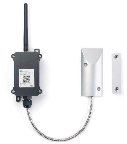
The Dragino NDS03A is an Open/Close NB-IoT Door Sensor. It detects door open/close status and uplinks to IoT server via NB-IoT network. NDS03A can connect two door sensors. user can see the door status, open duration, open counts in the IoT Server.
The NDS03A will send periodically data every 4 hours as well as for each door open/close action.
It also counts the door open times and calculates the last door open duration. Users can also disable the uplink for each open/close event, instead, NDS03A can count each open event and uplink periodically.
It supports sending data through UDP, MQTT and COAP over nb-iot.
Useful resources
Find here the useful resources:
Configuring the device
Register the device
The imei can be found on the top cover of the device, please register the device in your iotcreators project before attempting to connect the device to the network.
Register the device
Opening the device
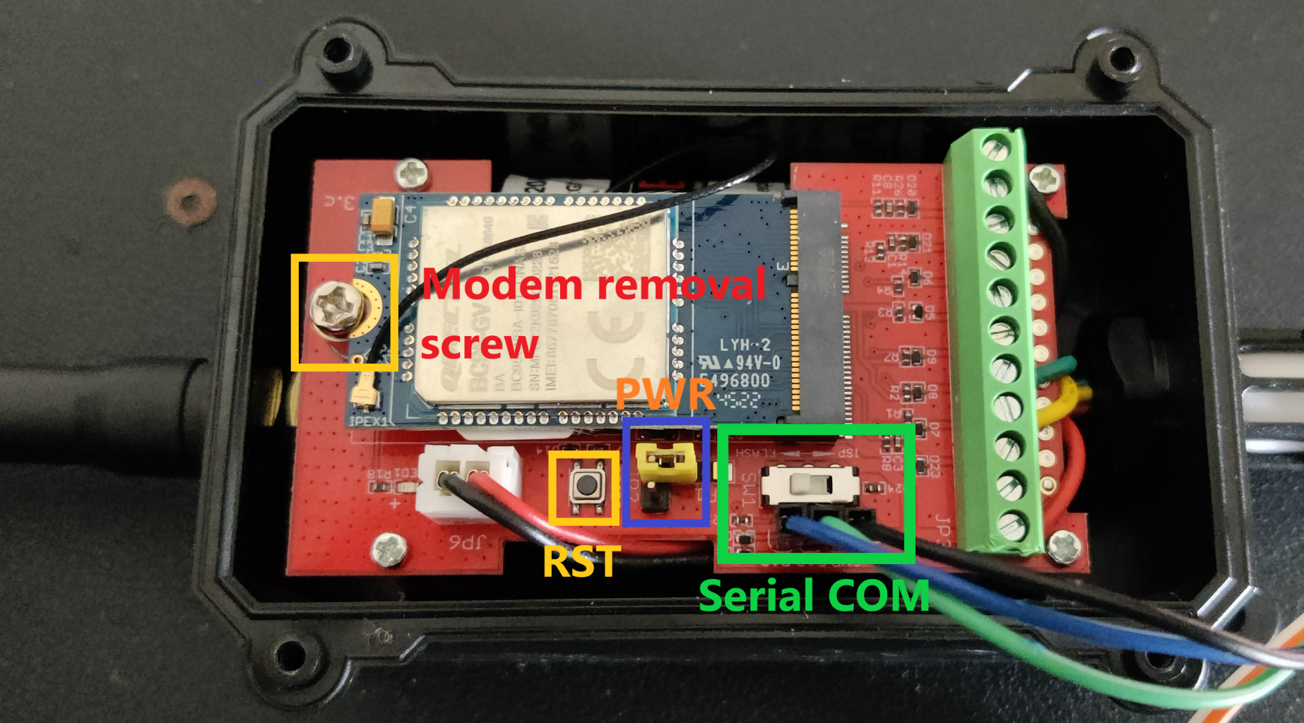
Connect the antenna to the device, then unscrew the four screws that hold the waterproof cover in place. This is the top view of the board:
Inserting the sim card
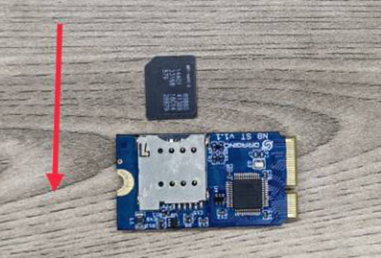
To mount the sim card into the sim card tray, unscrew the "modem removal screw" as showed above and insert the sim card.
Please be sure to insert the sim card as shown in this photo:
Connecting the device to a computer
To connect the device to a computer, you will need a usb to serial converter, which supports 3V3 or 5V logic. The logic voltage level can be selected with the "logic voltage switch" switch.
Set the correct voltage level
Please carefully setup the correct voltage level 3.3V according to your usb-to-serial converter. Failing to do so may unrecoverably damage your device!
You need 3 cables to connect the device to a serial monitor: GND (ground), TX (transmit) and RX (receive).
Just connect the PA3 of the dragino sensor serial COM to the TX of the usb-to-serial converter, the PA2 of the dragino sensor serial COM to the RX of the usb-to-serialconverter and the GND of the dragino sensor serial COM to the GND of the usb-to-serial converter.
Baudrate must be set to 9600 bps.
First startup
To boot up the device, please set up the power on jumper as shown in section "Opening the device" to power on the device. Please make sure that the device is correctly attached to a computer.
Open your favourite serial monitor (for example: miniterm on linux or arduino serial monitor on windows) and the device will start to output info about its startup like so:
16:24:32.861 -> [12589]NBIOT has responded.
16:24:37.191 -> [16922]Echo mode turned off successfully.
16:24:39.123 -> [18868]Model information:BC95-GV.
16:24:40.458 -> [20206]The IMEI number is:<your_imei_here>.
16:24:41.824 -> [21554]The IMSI number is:<your_imsi_here>.
16:24:43.157 -> Currently set frequency band:1,3,5,8,20,28
If the imsi is correctly read, it means that the sim card has been correctly inserted.
Enter configuration mode
To enter configuration mode, just input the correct password, which for this device is 12345678.
Just input
12345678
And if the password is correct, the device will respond
16:53:09.872 -> [122884]Password Correct
You can set a custom device ID (the default will be the device imei) with command
AT+DEUI=<device_id> (15 bytes)
This means you are not able to enter at commands to configure the device.
Setting network parameters
You will need to configure the usual iotcreators parameters in order to attach the device to the iotcreators, APN, server address and port, protocol. In this guide i will use UDP since it is the simplest one.
To configure the protocol, in this case we will use plain UDP, just input:
AT+PRO=2
To configure the APN (please take a look here to check the correct APN for your sim card, the one below is just an example) just input
AT+APN=scs.telekom.tma.iot
To configure the device to send data to the iotcreators UDP server, just input
AT+SERVADDR=172.27.131.100,15683
You can then restart the device with the reset button.The device will then try to attach to the network.
If the device fails to register to the network, thus you always receive signal strength indication = 99, it is likely that the device is not having enough time to register to it. In this case, you can issue command
AT+CSQTIME=10
Troubleshooting CSQ=99,99 error
Dragino hosts this page here to help you troubleshoot this issue.
To set the network registration timeout to 10 minutes, which should be sufficient to conenct to the network.
Sending data to iotcreators
Register the device
Remember to register the device before sending data to iotcreators, see chapter above.
The device will automatically send data at the specified interval of time. Such interval can be configured with command
AT+TDC=<time_in_seconds>
By default, the device will send an uplink message every 4 hour.
You can immediately send collected data with command
AT+NOUD
Payload decoding
For semplicity, only the case with a single door interrupt will be taken into account. You can set it to 1 interrupt with command:
AT+TTRCHANNEL=1
If set to 1, the only interrupt source will be pin pb14, otherwise they will be pb14 and pb15.
The uplink payload will include 26 bytes in total, with AT+TTRCHANNEL=1:
| Size (bytes) | 8 | 2 | 2 | 1 | 1 | 1 | 3 | 3 | 4 | 1 | 3 | 3 | 4 | 1-32 group (8 bytes each) |
|---|---|---|---|---|---|---|---|---|---|---|---|---|---|---|
| Value | IMEI | BAT | Version | Signal | MOD | Door status | Door open num (pb14) | Last open time (pb14) | UNIX timestamp | Door status | Door open num (pb14) | Last open time (pb14) | UNIX timestamp | ... |
The payload can be decoded as such, a payload example of:
f86778705021331700640ccf19010000000016000017637590df
Where
- Device ID: 0x f867787050213317 = f867787050213317
- Version: 0x0064=100=1.0.0
- BAT : 0x0ccf = 3279 mV = 3.279V
- Signal: 0x19 = 25
- Mod: 0x01 = 1
- Door Status: 0x00=0
- Alarm Status: 0x00 =0
- Door open num: 0x000016 =22
- Last open time: 0x000017 =23
- Timestamp: 0x637590df =1668649183 (Unix Time)
Convert UNIX timestamps to human readable timestamps
You can convert UNIX timestamps to human readable timestamps with this online tool here for example.
Code example
Here you can find a code example on how to decode data from this device:
Uplink decoder
Forwarding data to your application endpoint
To forward data to your application endpoint, you can follow the user guide here:
Forwarding data
Updated about 3 years ago