Wurth Elektronik eiSos GmbH: Adrastea-I
Introduction
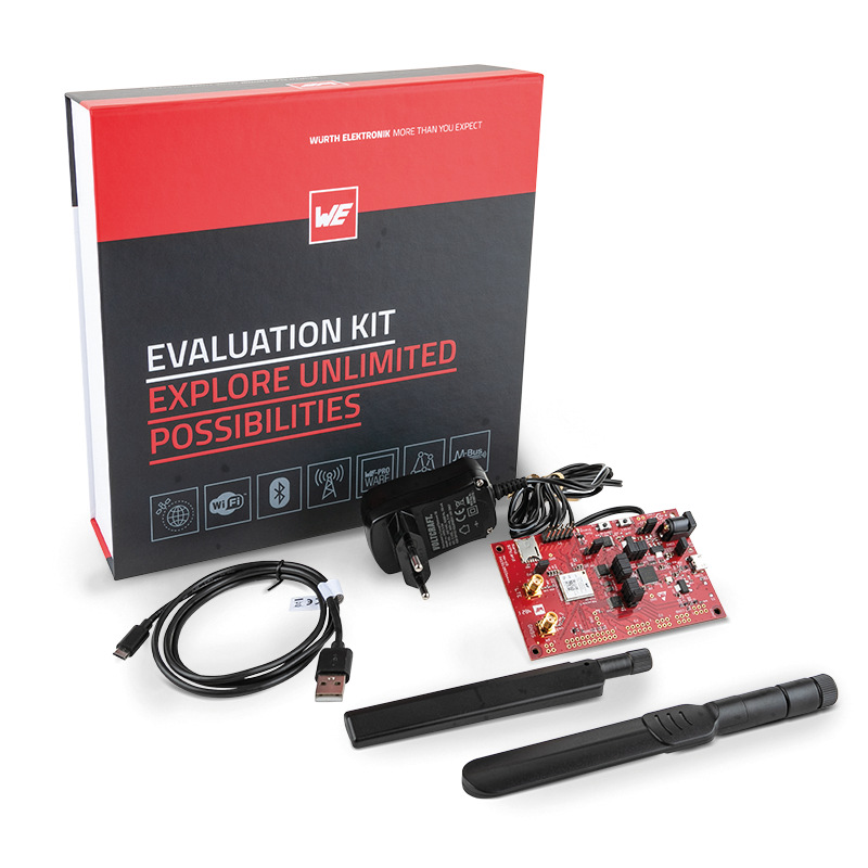
The Adrastea-I evaluation kit is the latest product from Wurth Elektronik eiSos GmbH. It supports Nb-IoT and LTE cat M1. It is based on the Adrastea-I modem and comes in this evaluation kit to ease the process of developing applications.

Wurth Elektronik eiSos GmbH Adrastea-I evaluation kit
Links*
| Titel | URL |
|---|---|
| Where can I get it from? | Get it from Wurth Elektronik eiSos GmbH website here: https://www.we-online.com/catalog/en/EVALBOARDS_CELLULAR_2 |
| Evaluation kit manual | https://www.we-online.com/catalog/manual/2615029236001_Manual-um-adrastea-i-ev-2615029236001-V1-0_rev1.0.pdf |
| Adrastea-I general manual | https://www.we-online.com/catalog/manual/2615011136000_Manual-um-adrastea-i-2615011136000-v1-0_rev1.0.pdf |
| Adrastea-I AT commands | https://www.we-online.com/catalog/media/o691492v8984%20Manual-um-acm-adrastea-i-2615011136000-V1-0%20%28rev1%29.pdf |
| Adrastea commander tool (it also contains the software manuals inside) | https://www.we-online.com/catalog/media/o691164v9184%20Adrastea%20Commander%20%28rev1%29.zip |
| FTDI drivers (drivers for the serial communication) | https://ftdichip.com/drivers/vcp-drivers/ |
Setup the Device
Before going through the steps, watch also this official video by Wurth Elektronik eiSos GmbH, it will give you a broader look at the board and tools.
Setup and presentation video
See below!
Before powering up the board
Do not power up the board without having connected Antennas before!
Install your nano sim card into the simtray, then connect the two antennas (the shorter one is for gnss and the longer one is the lte antenna).
Then, connect the power supply and the usb cable to your PC.
Installing Adrastea commander tool
First of all, install the Adrastea commander tool to ease the process of sending AT commands to the modem, you can download it from the link below. (you can also use other serial terminals if you prefer to)
Adrastea commander tool
Send AT Commands
Open Adrastea commander and connect to the board.
To enable the passthrough of at commands to the modem, (you can also send commmand "?" to the board to display a list of available commands), send command map as shown in the picture.
Having done that, you will be able to pass AT commands directly to the modem.
Attach to NB-IoT Network
This chapter explains how you can attach your Adrastea-I to an NB-IoT network.
Step 1: Set the modem in Nb-IoT mode.
AT%RATACT?
OK
AT%RATACT="NBIOT",1
With this modem, you don't need to set the bands because all the bands are already automatically searched.
Step 2: Configure the APN for your IoT creators SIM card and (opt). set the network to register to manually.
Choosing the correct APN for your sim card
The command below represent an example, different sim cards can have different APNs, for the correct APN check this doc page here: https://docs.iotcreators.com/docs/general-settings
AT%PDNSET=1,"cdp.iot.t-mobile.nl","IPV4V6"
OK
The modem is pre-configured to perform an automatic network operator selection based on the SIM card information. This is initiated once you turn on the radio functionality with +CFUN (refer to Step 3). If the SIM card in your region has no preferred mobile network operator listed, it can become necessary to manually select the network operator to connect to.
The AT+COPS command requires the use of the PLMN (Public Land Mobile Network) ID, e.g. 26201 for Telekom Deutschland. The list of all major PLMN IDs can be found at: https://en.wikipedia.org/wiki/Mobile_country_code
# T-Mobile Netherland
AT+COPS=1,2,"20416"
OK

# Telekom Deutschland
AT+COPS=1,2,"26201"
OK

# T-Mobile Poland
AT+COPS=1,2,"26002"
OK
In case you are interested in performing a network scan to see which network operators are visible with your Adrastea-I device, you can use the AT%COPS=? command. The command is blocking and may take multiple minutes in order to complete the full network scan.
Step 3: Finally, it is time to turn on the radio with AT+CFUN=1 and attach your device to the cellular network.
AT+CFUN=1
OK
Send and Receive Data via UDP Sockets
Once you are connected to your NB-IoT network, you may want to send some data to a server backend. The following chapter explains how to send a "Hello World" message from the Adrastea-I to the IoT Creators portal and vice versa.
Send "Hello World"
Register your device first!
Make sure that you have registered your device with its IMEI at the IoT Creators portal BEFORE you send your first message to the UDP or CoAP server of IoT Creators.
If you forget, you will have problems to register your device afterwards, you device will be temporarely blocked. In this case, please wait 10 minutes and your device will be automatically un-blocked, then you will be able to register it again to your profile.
Step 1: Open a UDP socket
First of all, check that you can reach the udp server with your device. To do so, please issue:
PING Service
Check the correct ping address here: IoT Configuration Parameter
AT%PINGCMD=0,"172.27.131.100"
If everything i correct, you will receive something like:
%PINGCMD:1,"172.27.131.100",1324,253
To Allocate socket session, here Destination IP Address: 172.27.131.100 Destination Port Number: 15683, issue
AT%SOCKETCMD="ALLOCATE",1,"UDP","OPEN","172.27.131.100",15683

response:
%SOCKETCMD:1
Then, check the socket status with
AT%SOCKETCMD?

which will probably get this response:
%SOCKETCMD:1,"DEACTIVATED"
To activate the socket, issue
AT%SOCKETCMD="ACTIVATE",1

OK
Step 2: Send "Hello World" to the IoT Creators server
Send data throught the newly-created socket with
AT%SOCKETDATA="SEND",1,13,"48656C6C6F2C20776F726C6421"

if everything went ok, response will be:
%SOCKETDATA:1,13

OK
The expected format data is in hex ascii string (2 bytes for every character)
Step 3: View the received message in the IoT Creators Portal
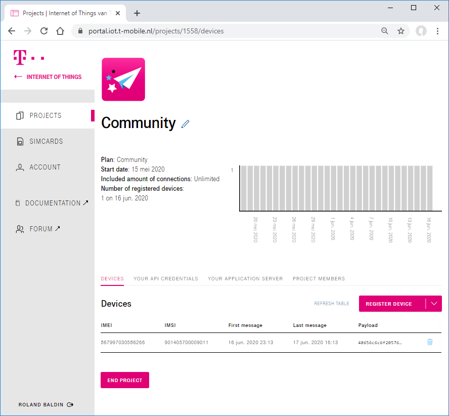
For each device the IoT Creators Portal makes the latest received message available by showing it in the Payload column.

If you click on the payload the value is automatically copied to your clipboard.
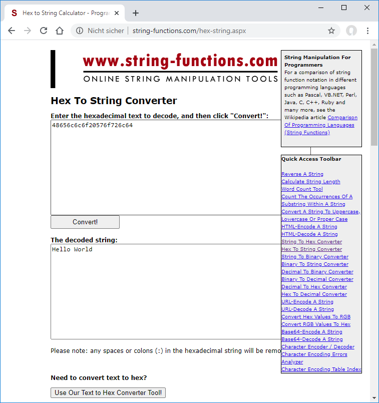
Our message/String Hello World will be displayed as 48656c6c6f20576f726c64 in the IoT Creators portal (hex encoded).
You can use an online tool as shown below to decode the received message from hex format to a readable string and check its content. Example Hex To String Converter: http://string-functions.com/hex-string.aspx.

If you can decode your received message to Hello World **CONGRATULATIONS**! You have just successfully sent your first UDP message over NB-IoT.
Receive "Hello Device"
Step 1: Prepare a UDP downlink message to be sent to the Adrastea-I
View your registered devices under your IoT Creators project. Next to your respective Adrastea-I device, click on "Actions" -> "Send a downlink message". Enter "Hello Device" as message and click on send. Please note that your message is queued for transmission and not directly transmitted to the Adrastea-I.
Click on Actions -> "Send a downlink message" next to your registered device.
Step 3: Send dummy data to the IoT creators portal
Sending some dummy data to the IoT Creators portal is required in order to trigger the transmission of the downlink message from the server queue to the end device, our Adrastea-I.
Step 4: Check if UDP data has been received
If udp socket has some bytes to be read in it (e.g. it has received some bytes), it will inform the host controller in this way.
%SOCKETEV:1,1
To read bytes from the socket, issue:
AT%SOCKETDATA="RECEIVE",1,10

response will look like this:
%SOCKETDATA:1,10,0,"68656C6C6F6465766963","172.27.131.100",15683
Where 10 in this case means that we want to read 10 bytes.
You should now see your UDP message from the IoT creators portal in the AT command response.
MQTT
Sending uplinks through MQTT
To send uplinks through MQTT, you must first configure the port, with this command:
AT%MQTTCFG="IP",0,0,0,1883
Then, configure the device password, client_id and username with this command:
AT%MQTTCFG="NODES",0,"<imei_of_the_device>","172.27.130.11","<imei_of_the_device>","password"
Then, to connect to the broker, just issue:
AT%MQTTCMD="CONNECT",0
Then, to publish messages to the device topic, which will be always "us/<imei_of_the_device>", just issue:
AT%MQTTCMD="PUBLISH",0,1,0,"us/359100540000267",<lenght_in_byte>
{"uplinkMsg/0/data": "Hello"}
Message payload format
Message payload must be in next line in respect to the command, and must be in the form of:
{"uplinkMsg/0/data": "<message_payload>"}
Useful general commands
AT%RATACT? //display the current modem operation mode, either CATM or NBIOT
AT+CFUN=0 //turn off the radio
ATZ //reboot the modem
AT+CGSN=1 //display the imei
AT%CCID //display iccid
at+cops? //displays the current connected network (if any)
AT%PDNSET? // displays the current configured apn
Low power features
Check this guide for the Wurth Elektronik eiSos GmbH Adrastea-I low power features:
Wurth Elektronik eiSos GmbH adrastea-I low power features
https://docs.iotcreators.com/docs/low-power-features#wurth-elektronik-eisos-gmbh-adrastea-i
Other useful functions
Retrieve time from the network
You can retrieve the local time from the network (not all mobile networks support this command) by issuing:
AT+CCLK?

+CCLK: 2023/02/06,13:17:08GMT+1
Updated over 2 years ago
