X-Logic NB-IOT pulse meter
The X-LOGIC nb-iot pulse meter is a device that can be connected to an existing meter (water, electricity, gas, etc.) to make it smart and be able to send data on UDP over a low power cellular connection.
It will read the impulses coming from the meter on its inputs and send the value read every defined time.
Useful resources
You can find the datasheet here
Connecting to iotcreators
To connect to iotcreators, you will have 2 options:
- Contact directly x-logic and they will configure the device to connect to iotcreators
- Configure the device yourself, through the serial communication.
Configure the device with serial communication
First of all, the device must be provisioned on the iotcreators portal as UDP device. The imei of the device can be found on the external box. You can follow this guide here: https://docs.iotcreators.com/docs/3-register-devkit
Register the device before turning it on
Please register the device to iotcreators before turning it on, otherwise it will be blacklisted for 10 minutes
Connecting to the computer
To enter device configuration mode, attach it through a ttl uart to usb with the rx and tx pin, set baudrate to 9600bps and short the rst pin to ground.
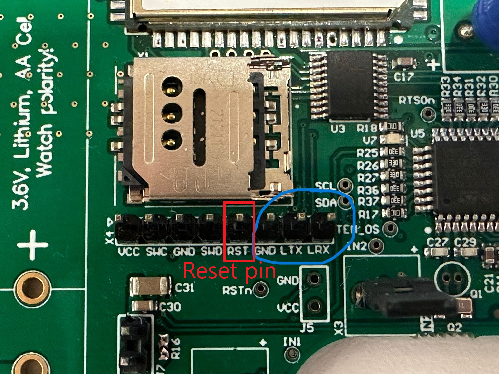
The device will reboot, you must type "start" within 10 seconds to enter the configuration mode. You can reset the board by shorting the RST pin to ground in case you miss the time window.
Type "help" to display the available commands.
Available commands
10:15:42.314 -> start
10:15:42.314 -> Command interface started
10:15:42.314 -> Write command ('help' for a list of commands)
10:15:42.382 -> > help
10:15:48.874 ->
10:15:48.874 -> COMMANDS
10:15:48.874 -> NAME                    ARGUMENTS
10:15:48.874 -> help                    0
10:15:48.909 -> exit                    0
10:15:48.942 -> mode                    1
10:15:48.977 -> tamperReset             0
10:15:49.011 -> restart                 0
10:15:49.045 -> timestamp               1
10:15:49.080 -> scheduleTime            1
10:15:49.080 -> factoryReset            0
10:15:49.115 -> counterReset            1
10:15:49.149 -> getImpulses             0
10:15:49.183 -> setAppEui               1
10:15:49.183 -> getAppEui               0
10:15:49.218 -> setAppKey               1
10:15:49.252 -> getAppKey               0
10:15:49.287 -> setDevAddr              1
10:15:49.320 -> getDevAddr              0
10:15:49.355 -> setAppSKey              1
10:15:49.355 -> getAppSKey              0
10:15:49.390 -> setNwkSKey              1
10:15:49.424 -> getNwkSKey              0
10:15:49.459 -> setApn                  1
10:15:49.492 -> getApn                  0
10:15:49.527 -> setUser                 1
10:15:49.527 -> getUser                 0
10:15:49.561 -> setPass                 1
10:15:49.595 -> getPass                 0
10:15:49.629 -> setLoraMode             1
10:15:49.629 -> setDataRate             1
10:15:49.664 -> setServerIP             1
10:15:49.699 -> getServerIP             0
10:15:49.732 -> setServerPort           1
10:15:49.766 -> getServerPort           0
10:15:49.800 -> setTamperTime           1
10:15:49.834 -> getTamperTime           0
10:15:49.834 -> enableConfMsgs          1
10:15:49.869 -> setPSM                  1
10:15:49.904 -> getPSM                  0
Connecting to iotcreators
To set the APN (check this page https://docs.iotcreators.com/docs/general-settings for the APN to configure ), just type:
setApn scs.telekom.iot.tma
To set the iotcreators UDP address, just type
setServerIP 172.27.131.100
Then, to set the port:
setServerPort 15683
Then, just type
restart
Uplinks
Device will be shipped in deactivated mode, to preserve the battery. Thus, until a pulse is detected, the device will not send regular nor tamper uplinks. If you want to create a "fake" inpulse for testing, you can short-circuit the IN2 or IN1 input. Then, you can create a tamper by short-circuiting IN3 input. The device will send this tamper uplink immediately.
Types
There are two types of uplinks:
- Regular message
- Tamper message
Regular message
Regular messages are sent in regular, defined intervals. Available intervals are 1h, 2h, 4h, 8h, 12h, 24h and 48h. If
so configured, message sending can be initiated in a specific time of a day, and subsequent messages are sent
afterwards in defined time interval. If time of the day to send message is not defined, interval is calculated from
the device activation.
Tamper message
Tamper message is sent immediately after tamper detection. This message is independent from regular messages.
Structure
Uplink structure
You can find information about the uplink notation in chapter 8.2 of the datasheet.
Decoding data
You can also refer to this piece of code (pyhton) to decode data coming from the device, as coming from the iotcreators backend.
    def decode(self, data):
    # data is a hex string representing the payload sent by the device,
    # as output by iotcreators backend when forwardign the message to the customer application endpoint
        try:
            byte_array = bytes.fromhex(data)
            data_decoded = byte_array.decode('utf-8')
            imei_start = data_decoded.find("IMEI: ")
            imei = data_decoded[imei_start + 6:imei_start + 21]
            params = {"imei": imei}
            msg = ""
            tamper = 0
            voltage = 0
            impulse1 = 0
            impulse2 = 0
            send_mode_parsed = ""
            temperature = 0
            mode = 0

            if (len(byte_array)) > 58:
                impulse1 = byte_array[3] << 24 | byte_array[2] << 16 | byte_array[1] << 8 | byte_array[0]
                impulse2 = byte_array[7] << 24 | byte_array[6] << 16 | byte_array[5] << 8 | byte_array[4] << 0

                data_as_int = [b for b in byte_array]
                voltage = byte_array[8] + 200
                mode = int(data_as_int[9])
                tamper = int(data_as_int[10])
                temperature = int(data_as_int[11])
                if mode == 0:
                    send_mode_parsed = "1h"
                if mode == 1:
                    send_mode_parsed = "2h"
                if mode == 2:
                    send_mode_parsed = "4h"
                if mode == 3:
                    send_mode_parsed = "8h"
                if mode == 4:
                    send_mode_parsed = "12h"
                if mode == 5:
                    send_mode_parsed = "24h"
                if mode == 6:
                    send_mode_parsed = "48h"
                msg = ""
                if tamper & 0b10000000:
                    msg = msg + "Tamper message\n"
            else:
                msg = msg + "Regular message\n"
            if tamper & 0b00000100:
                msg = msg + " Acc tamper active\n"
            if tamper & 0b00000010:
                msg = msg + " IN3 tamper active\n"
            if tamper & 0b00000001:
                msg = msg + " IN1 tamper active\n"

            decoded = {
                "voltage": voltage,
                "temperature": temperature,
                "tamper": tamper,
                "impulse1": impulse1,
                "impulse2": impulse2,
                "send_mode_parsed": send_mode_parsed,
                "mode": mode,
                "msg": msg,
                "params": params
            }
        except Exception as ex:
            print(f"unable to parse data, detected exception {str(ex)}")
            decoded = {}

        return decoded
Forwarding the uplinks to your application endpoint
Follow the guide here to forward the uplinks to your application endpoint:
Forward to application endpoint
Downlinks
Downlinks can be used to configure the device in different parameters.
Downlinks length
Downlinks length must not be longer than 8 bytes.
Downlink structure
You can find information about the possible downlinks that can be sent in chapter 8.1 of the datasheet.
Sending downlinks
To send downlinks to the device, you can use the portal or the api here: https://dash.readme.com/project/iotcreators/v2.2/refs/send-standard-downlink